
당신은 주제를 찾고 있습니까 “every control ec 6 180 instrukcja – hướng dẫn sử dụng hàm FC105 \u0026 FC106 SCALE BLOCKS trong PLC S7 300“? 다음 카테고리의 웹사이트 th.taphoamini.com 에서 귀하의 모든 질문에 답변해 드립니다: th.taphoamini.com/wiki. 바로 아래에서 답을 찾을 수 있습니다. 작성자 Vo An 이(가) 작성한 기사에는 조회수 2,024회 및 좋아요 25개 개의 좋아요가 있습니다.
Table of Contents
every control ec 6 180 instrukcja 주제에 대한 동영상 보기
여기에서 이 주제에 대한 비디오를 시청하십시오. 주의 깊게 살펴보고 읽고 있는 내용에 대한 피드백을 제공하세요!
d여기에서 hướng dẫn sử dụng hàm FC105 \u0026 FC106 SCALE BLOCKS trong PLC S7 300 – every control ec 6 180 instrukcja 주제에 대한 세부정보를 참조하세요
#siemens#plc#thanhanvo
hướng dẫn nhỏ về PLC S7-300, các bạn thấy hay hãy đăng ký kênh giúp mình
every control ec 6 180 instrukcja 주제에 대한 자세한 내용은 여기를 참조하세요.
EVCO EC6180 User Manual | 2 pages – manualsdir.com
EC 6-180. EC 6-180. EC 6-180. EC 6-180. EC 6-180. ON-OFF digital thermostat for compressor,. evaporator fans and defrost (for temperature-. time) management.
Source: www.manualsdir.com
Date Published: 10/30/2021
View: 6970
EV3 Basic Split – Every Control
Touch the SET key (or take no action for 15 s). 4.5. Activating manual defrost (if r5 = 0, default). Check that the keypad is not locked and that overcooling is …
Source: www.everycontrol.com.br
Date Published: 11/14/2021
View: 9067
EV6 – 223 – ARKTON
w razie napraw należy skontaktować się siecią sprzedaży Evco … +48 (22) 727 84 97, fax +48 (22) 736 28 99, www.berling.pl, e-mail: [email protected]. 6.
Source: arkton.pl
Date Published: 2/12/2022
View: 5786
EV3294 – gev-online.com
I. ENGLISH. – controller for low temperature units. – power supply 115… 230 VAC. – cabinet probe and evaporator probe (PTC/NTC). – door switch input. -.
Source: www.gev-online.com
Date Published: 8/12/2021
View: 4738
FK 400 T – entro.pl
EVERY CONTROL S.r.l. … Mocowanie w panelu, w wycięciu o wymiarach 71 x 29 mm (2,79 x 1,14 cala) za pomocą … 6 = alarm niskiej temperatury zdefiniowanej.
Source: www.entro.pl
Date Published: 3/3/2021
View: 6618
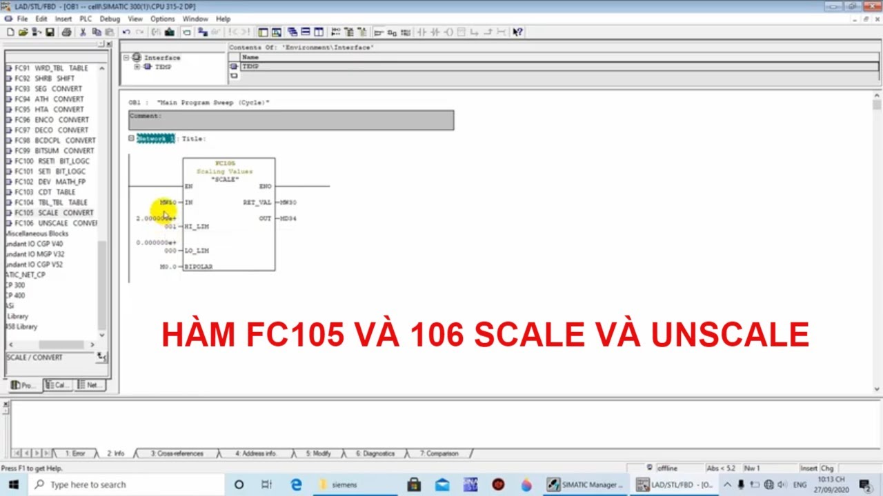
주제와 관련된 이미지 every control ec 6 180 instrukcja
주제와 관련된 더 많은 사진을 참조하십시오 hướng dẫn sử dụng hàm FC105 \u0026 FC106 SCALE BLOCKS trong PLC S7 300. 댓글에서 더 많은 관련 이미지를 보거나 필요한 경우 더 많은 관련 기사를 볼 수 있습니다.
주제에 대한 기사 평가 every control ec 6 180 instrukcja
- Author: Vo An
- Views: 조회수 2,024회
- Likes: 좋아요 25개
- Date Published: 최초 공개: 2020. 9. 28.
- Video Url link: https://www.youtube.com/watch?v=l1ML0KgsCmo
EVCO EC6180 User Manual
EC 6-180
EC 6-180
EC 6-180
EC 6-180
EC 6-180
ON-OFF digital thermostat for compressor,
evaporator fans and defrost (for temperature-
time) management
Operating instructions
Version 1.00 of November the fourteenth 2002
File ec6180e_v1.00.pdf
PT
IMPORTANT:
The use of this new instrument is easy; but for safety reasons, it is
important read these instructions carefully before the installation or
before the use and follow all additional informations.
It is very important keep these instructions with the instrument for future
consultations.
ENGLISH
GENERAL INFORMA
GENERAL INFORMA
GENERAL INFORMA
GENERAL INFORMA
GENERAL INFORMATIONS
TIONS
TIONS
TIONS
TIONS
WHAT IS THE USE
EC 6-180 is an ON-OFF digital thermostat studied for refrigerating systems management through
the compressor, evaporator fans and defrost (for temperature-time) management.
In factory the instrument gets preset to accept at the measure inputs PTC/NTC probes used in
refrigeration field at the moment.
Some parameters permit to set the thermostat to protect the compressor against overloads
due to several starts repeated in a short time, to manage the defrost according with one’s
requirements, to establish the evaporator fans output functioning, to signal working condi-
tions outside the safety limits.
EC 6-180 is available in the 53 x 90 mm (2.08 x 3.54 in., 3 DIN modules) case and it is studied
for DIN standard rail installation.
GETTING ST
GETTING ST
GETTING ST
GETTING ST
GETTING STAR
AR
AR
AR
ARTED
TED
TED
TED
TED
INSTALLATION
EC 6-180 was studied for DIN EN 50022 standard rail installation according with DIN 43880
norms (the overall dimensions are related in Fig. 3, the fixing system suggested by the builder
is related in Fig. 4).
ADDITIONAL INFORMATIONS
–
verify if the using conditions (ambient temperature, humidity, etc.) are within the
limits indicated by the builder (see the chapter TECHNICAL DATA)
–
install the instrument in a location with a suitable ventilation, to avoid the internal
overheating of the instrument
–
do not install the instrument near surfaces that can to obstruct the air-grating (car-
pets, covers, etc.), heating sources (radiators, hot air ducts, etc.), locations sub-
ject to direct sunlight, rain, humidity, excessive dust, mechanical vibrations or
bumps, devices with strong magnetos (microwave ovens, big speakers, etc.)
–
according with the safety norms, the protection against possible contacts with
electrical parts and parts protected with functional insulation only must be ensured
through a correct installation procedure of the instrument; all parts that ensure the
protection must be fixed so that they can not be removed if not with a tool.
ELECTRICAL CONNECTION
EC 6-180 is provided with four screw terminal blocks for cables up to 2.5 mm² (0.38 in.², for
the connection to the power supply, inputs and outputs), it is provided with one three poles
single line male connector (for the connection to the remote indicator) and it is provided with
one five poles single line female connector (for the connection to the CLONE configurer/cloner
and RICS supervision systems), located on the instrument frontal panel (the connections to
derive are related in Fig. 5 and they are checkable on the polyester label stuck on the instru-
ment case).
ADDITIONAL INFORMATIONS
–
if the instrument is brought from a cold to a warm location, the humidity may
condense inside the instrument; wait about an hour before supply the instrument
–
verify if the operating power supply voltage, electrical frequency and power of
the instrument correspond to the local power supply (see the chapter TECHNICAL
DATA)
–
do not supply more instruments with the same transformer
–
if the instrument is installed on a vehicle, its power supply must be derived di-
rectly from the battery of the vehicle
–
give the instrument a protection able to limit the current absorbed in case of
failure
–
the instrument remains connected to the local power supply as long as the termi-
nals 75 and 77 are derived to the local power supply, even if the instrument is
apparently turned off
–
give the probes a protection able to insulate them against possible contacts with
metal parts or use insulated probes
–
give the outputs a protection able to protect them against short circuit and overload
–
do not try to repair the instrument; for the repairs apply to highly qualified staff
–
if you have any questions or problems concerning the instrument please consult
Fig. 1
f6-180.wmf
Every Control (see the chapter BUILDER DATA).
USE
USE
USE
USE
USE
PRELIMINARY INFORMATIONS
After derived the connections related in Fig. 5, during the normal functioning the instrument
displays the temperature read by the cabinet probe.
If an alarm should be active the instrument displays the alarm code flashing and the buzzer
utters an intermittent beep as long as the cause that has given it does not disappear (see the
chapter SIGNALS AND ALARMS); pressure on the key T1 during an alarm permits to silence
the buzzer.
EC 6-180 is provided with one working setpoint and with some configuration parameters that
get stored in a non volatile memory and that permit to set the instrument according with one’s
requirements (see the chapter CONFIGURABILITY).
The output K 1 is associated to the compressor and to the working setpoint, it remains acti-
vated continuously as long as the temperature read by the cabinet probe reaches the working
setpoint and when it rises above the working setpoint of the hysteresis value (differential) the
output gets reactivated, except during a defrost and a dripping.
The output K 2 is associated to the evaporator fans and it is forced to the status ON, except
during a dripping and except what established with the parameters of the family F.
Passed the defrost interval from the moment of the instrument start or from the moment in
which the instrument presents a request of a defrost cycle, if the conditions permit it (the
temperature read by the evaporator probe must be below the defrost stopping setpoint) the
instrument automatically presents the following request of a defrost cycle.
A defrost cycle provides three phases (defrost, dripping and evaporator fans stoppage) con-
nected in cascade since the end of one automatically determines the passage to the following
one.
The output K 3 is associated to the defrost and it remains continuously activated during the
defrost as long as the temperature read by the evaporator probe reaches the defrost stopping
setpoint when the defrost ends and the instrument automatically moves to the dripping; if the
instrument was set to manage defrost to resistances (electrical) during a defrost the output K 1
gets forced to the status OFF, if the instrument was set to manage hot gas defrost (reversal of
cycle) during a defrost the output K 1 remains continuously activated.
Passed the dripping length from the moment of the defrost end the instrument automatically
moves to the evaporator fans stoppage; during a dripping the outputs K 1 and K 2 get forced to
the status OFF.
Passed the evaporator fans stoppage length from the moment of the dripping end the defrost
cycle ends; during an evaporator fans stoppage the output K 2 activation gets disabled.
If the conditions permit it (the temperature read by the evaporator probe must be below the
defrost stopping setpoint) keeping pushed the key T2 for four seconds at least or activating the
remote defrost digital input the instrument presents a request of a defrost cycle.
WORKING SETPOINT SETTING (WORKING TEMPERATURE)
To modify the working setpoint value keep pushed the key T3 (the instrument displays the
actual value) and at the same time push and release over and over the key T1 or T2 as long as
the instrument displays the desired value (keeping pushed the key T1 or T2 the value gets
decreased or increased more quickly): after the modification release the key T3 last; during the
pressure of the key T3 the LED L1 flashes quickly to indicate that a working setpoint setting
procedure is running (to the release of the key T3 the instrument automatically turns out from
1
4
Fig. 2
iu6180.wmf
DIMENSIONAL DA
DIMENSIONAL DA
DIMENSIONAL DA
DIMENSIONAL DA
DIMENSIONAL DAT
TT
T
TA
A
A
A
A
OVERALL DIMENSIONS
The dimensions are expressed in millimetres and inches (third-scale drawing).
Fig. 3
ds63me.wmf
INST
INST
INST
INST
INSTALLA
ALLA
ALLA
ALLA
ALLATION
TION
TION
TION
TION
WITH THE FIXING SYSTEM SUGGESTED BY THE BUILDER
On DIN EN 50022 standard rail according with DIN 43880 norms (third-scale drawing).
Fig. 4
ms63m.wmf
ELECTRICAL CONNECTION
ELECTRICAL CONNECTION
ELECTRICAL CONNECTION
ELECTRICAL CONNECTION
ELECTRICAL CONNECTION
CONNECTIONS TO DERIVE
Instance of typical application.
BUILDER DA
BUILDER DA
BUILDER DA
BUILDER DA
BUILDER DAT
TT
T
TA
A
A
A
A
EVERY CONTROL S.r.l.
Via Mezzaterra 6, 32036 Sedico Belluno ITALY
Phone 0039/0437852468 (a.r.) Fax 0039/043783648
Internet addresses
e-mail: [email protected]
http://www.everycontrol.it
TO BE CAREFUL
This publication exclusively belongs to EVERY CONTROL and shall not be reproduced and distributed if not expressly authorized by the same EVERY CONTROL.
EVERY CONTROL does not assume any responsibility in order to the characteristics, to the technical data and to the possible mistakes related herein or deriving from the use of the same.
EVERY CONTROL can not be considered responsible for damages caused from the inobservance of the additional informations.
EVERY CONTROL reserves the right to make any modification without prior notice and at any time without prejudice the basic functioning and safety characteristics.
Fig. 5
c6-180e.wmf
키워드에 대한 정보 every control ec 6 180 instrukcja
다음은 Bing에서 every control ec 6 180 instrukcja 주제에 대한 검색 결과입니다. 필요한 경우 더 읽을 수 있습니다.
이 기사는 인터넷의 다양한 출처에서 편집되었습니다. 이 기사가 유용했기를 바랍니다. 이 기사가 유용하다고 생각되면 공유하십시오. 매우 감사합니다!
사람들이 주제에 대해 자주 검색하는 키워드 hướng dẫn sử dụng hàm FC105 \u0026 FC106 SCALE BLOCKS trong PLC S7 300
- tia portal v16
- tia portal v16 download
- tia portal
- siemens
- thuan automation
- autocad electrical 2020
- autocad electrical 2020 youtube
- plc
- plc programming
- plc training
- plc ladder logic
- siemens ag
- siemens phone evolution 2020
- ausbildung bei siemens
- pid
- pid controller
- pid control
- pelvic inflammatory disease
- fc105 & fc106 scale
- step 7
- scale
hướng #dẫn #sử #dụng #hàm #FC105 #\u0026 #FC106 #SCALE #BLOCKS #trong #PLC #S7 #300
YouTube에서 every control ec 6 180 instrukcja 주제의 다른 동영상 보기
주제에 대한 기사를 시청해 주셔서 감사합니다 hướng dẫn sử dụng hàm FC105 \u0026 FC106 SCALE BLOCKS trong PLC S7 300 | every control ec 6 180 instrukcja, 이 기사가 유용하다고 생각되면 공유하십시오, 매우 감사합니다.